Description
This document describes the types of indicators and signs.
Not what you are looking for? See more NSG Rules
Purpose
To describe the types of indicators and signs used in the Network.
The figures in this Rule show examples of the indicators and signs used in the Network. White or lunar white lights are shown in blue  .
.
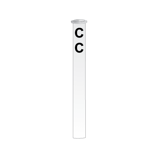
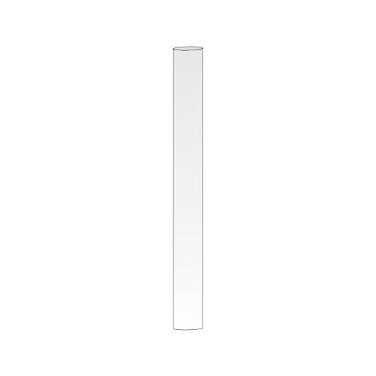
Clearance posts
Clearance posts may be located between two converging lines to show the clearance limit.
Some clearance posts have:
- a reflective background, or
- a white light that must be illuminated at night or in conditions of low visibility.
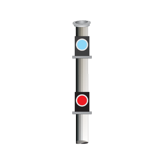
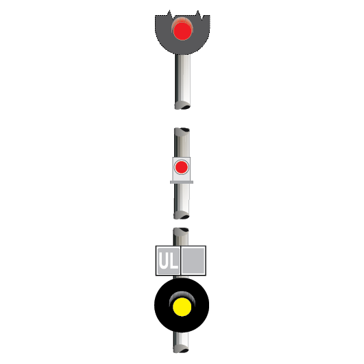
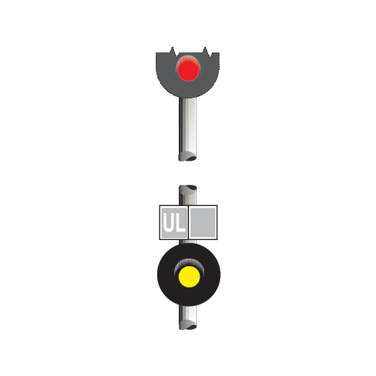
Dead end lights
Dead end lights are small red lights to indicate the end of dead end sidings. The lights display STOP indications only.
If it is possible for a dead end light to be mistaken as a running signal at STOP, a white light above the red light is used to distinguish it from a running signal.
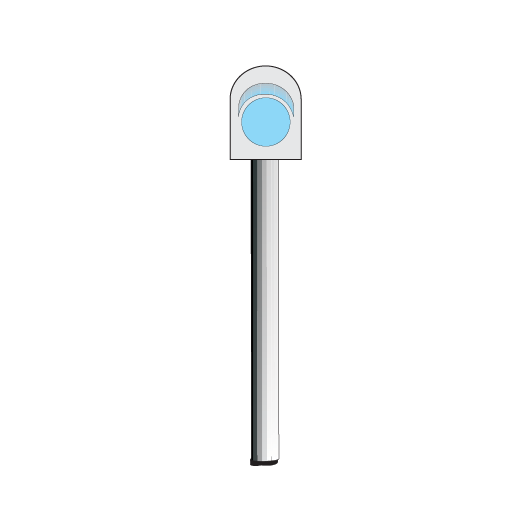
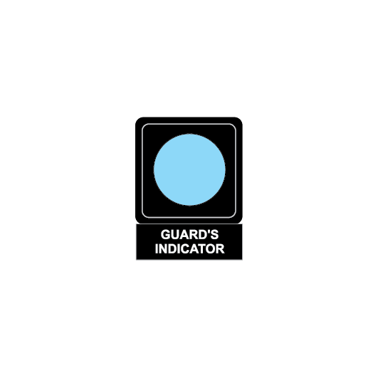
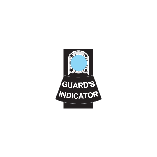
Guard’s indicator
If it is possible for the signal at the exit-end of a platform to be obscured from a Guard’s view, a Guard’s indicator is placed over the platform.
If the exit-end signal displays a PROCEED indication, a Guard’s indicator shows a lunar white or a blue light.
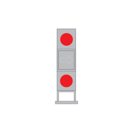
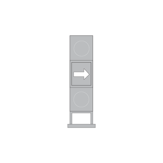
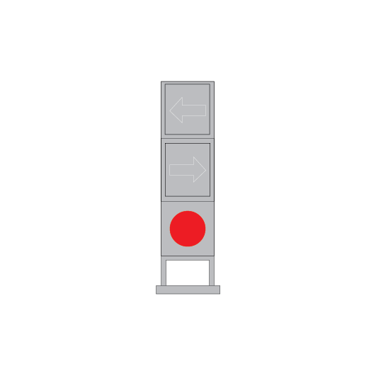
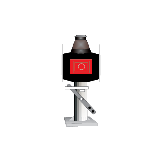
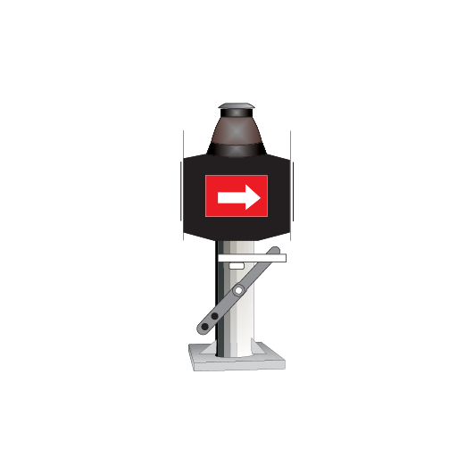
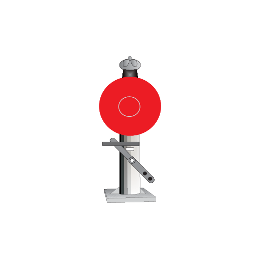
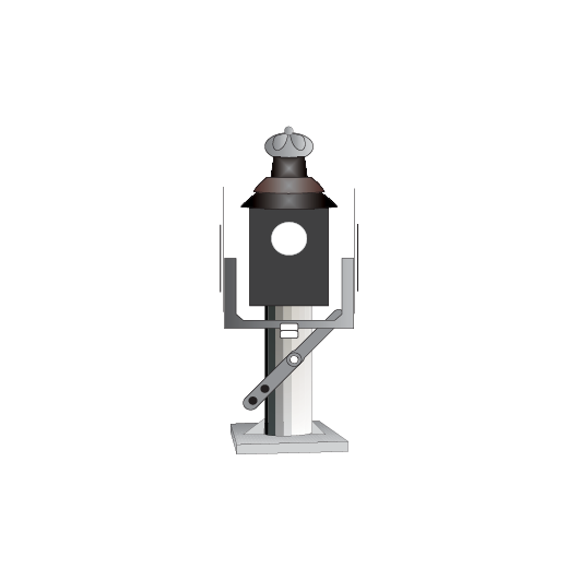
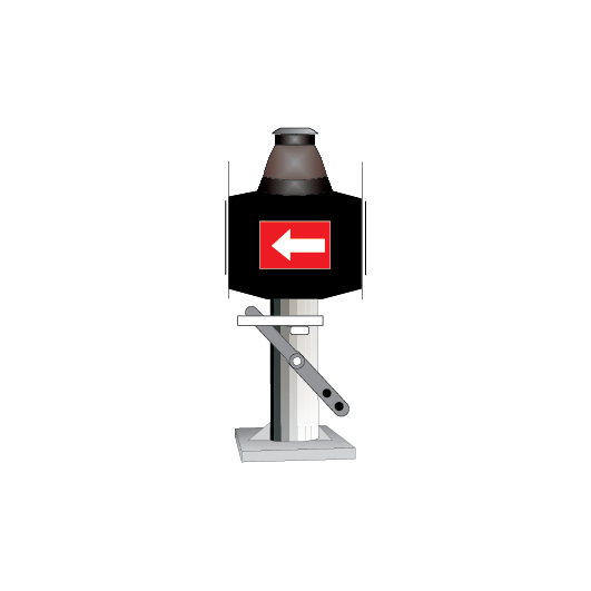
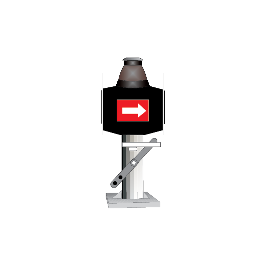
Point and catch point indicators
Point indicators are used to indicate the position of points. Catch point indicators show the position of catch points.
Point indicators and catch point indicators may be:
- colour light, or
- mechanical.
If the indicator displays:
- a red light, the points are not set
- a white arrow, the points are set for the route indicated by the direction of the arrow.

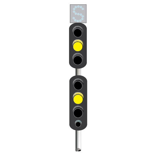
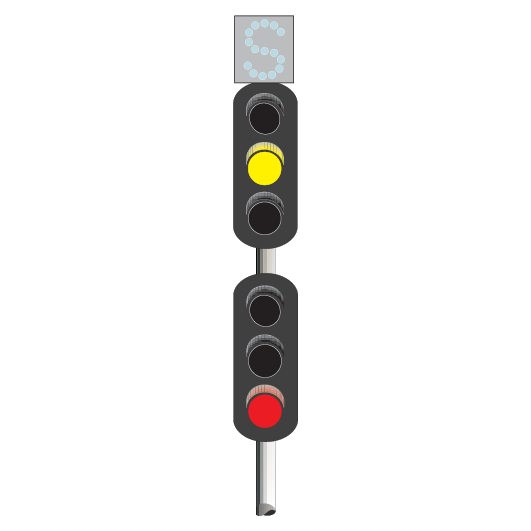
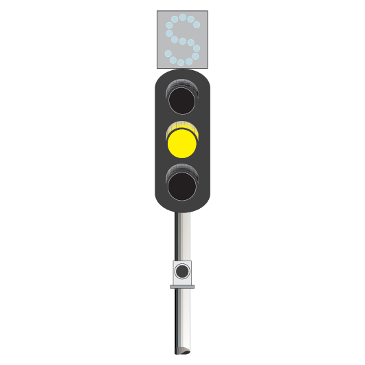
Route indicators
In single and double light colour light signalled territory, route indicators on running signals indicate, in most cases, the turnout route.
If the signal displays a PROCEED indication, the route indicator shows:
- letters, usually related to the name of a line, as in ‘S’ for Suburban, and ‘UM’ for Up Main, or
- numbers, usually referring to the number of a station platform, as in ‘3’ for the line beside Platform 3.
Route indicators on shunting signals or co-acting signals may show:
- a running line turnout route, or
- a shunting route.
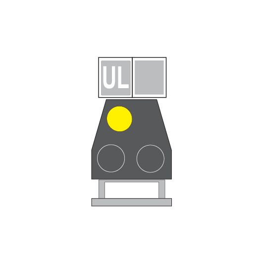
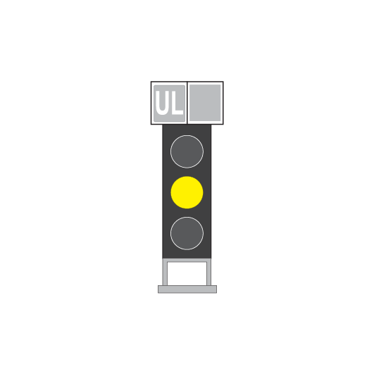
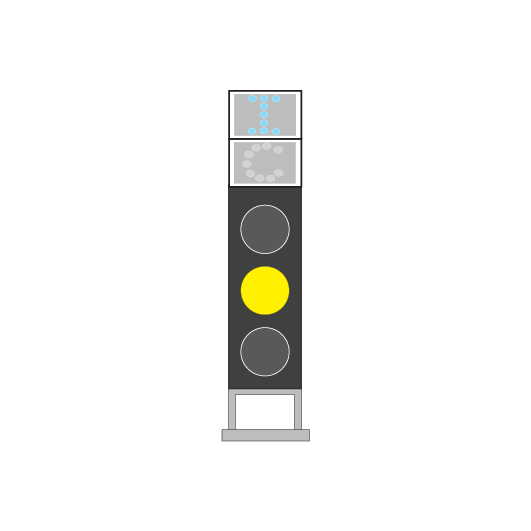
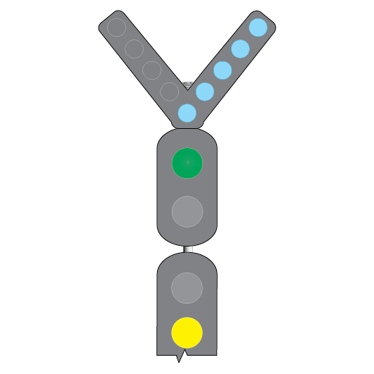
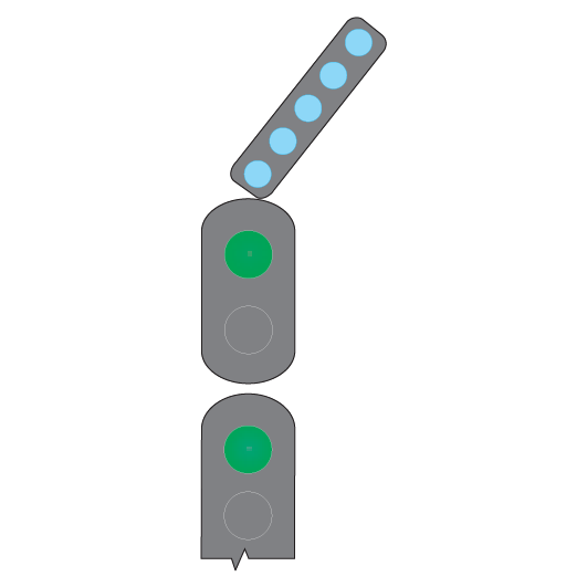
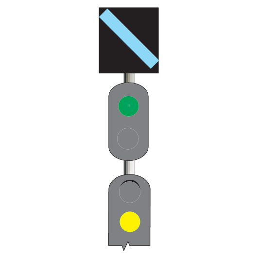
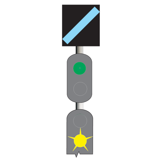
Turnout repeaters
Turnout repeaters are placed at braking distance from points to give advance warning that a turnout route is set.
They have one or more diagonal bars of white lights, in a separate unit fixed to the signal. The lights are angled up towards the turnout route.
If the turnout signal is at STOP, the turnout repeater on the preceding signal does not illuminate.
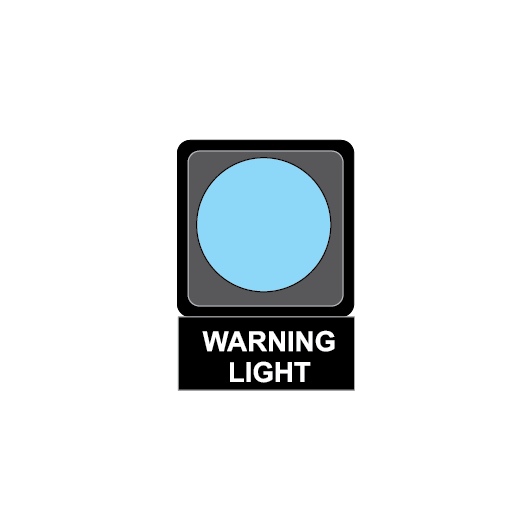
Warning lights and alarms
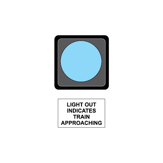
Illuminated white or orange warning lights are provided at locations where workers on track have a restricted view of approaching rail traffic. If rail traffic approaches, the lights go out.
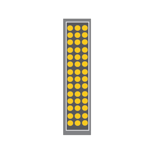
Illuminated white crossing lights, sometimes combined with audible warning devices as additional alarms, are provided at pedestrian crossings restricted to use by rail workers.
If rail traffic approaches, the lights go out and alarms are activated in time for workers to go to, or remain in, a safe place.
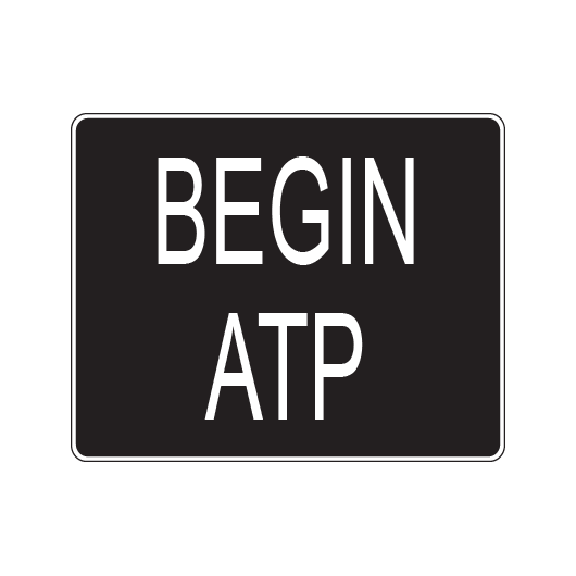
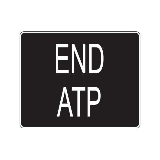
Automatic train protection (ATP) level border signs
ATP level border signs indicate the borders between track fitted with ATP trackside equipment (ATP level 1) and track not fitted with ATP trackside equipment (ATP level 0).
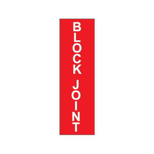
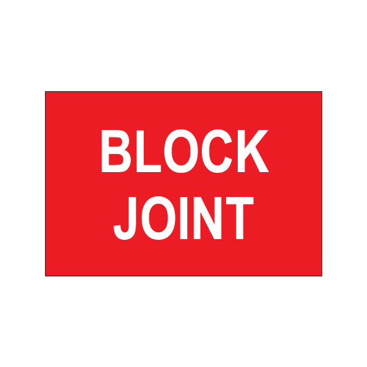
BLOCK JOINT signs
BLOCK JOINT signs:
- show the locations of insulating block joints between separate track-circuits of track-circuited line
- have white text on a red reflective background.
Signallers may require rail traffic to stand clear of a block joint.
BLOCK POST signs
Block post signs are used during manual block working and pilot staff working where a block post location is established.

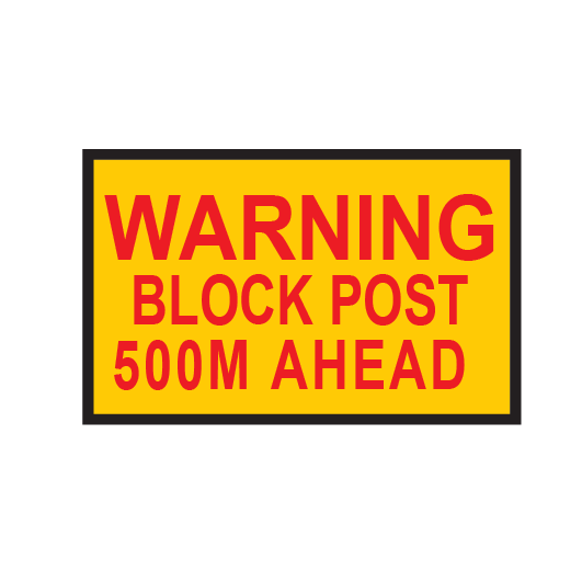
BLOCK POST WARNING signs
BLOCK POST WARNING signs are used if a block post location is established.
BLOCK POST WARNING signs are placed at least 500m before a block post location and act as reminder that a block post is located ahead.
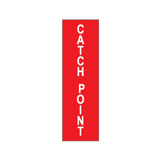
CATCH POINT signs
CATCH POINT signs:
- indicate that there are catch points ahead, and
- have white text on a red reflective background, and
- are provided where catch points are not protected by a fixed signal or an indicator.
Qualified Workers must check that catch points are closed correctly before a shunting movement begins.

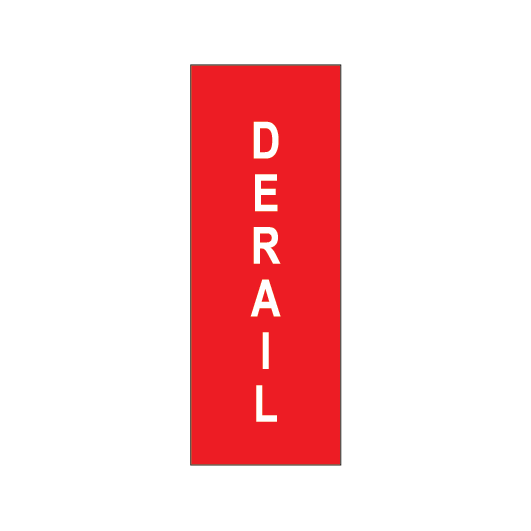
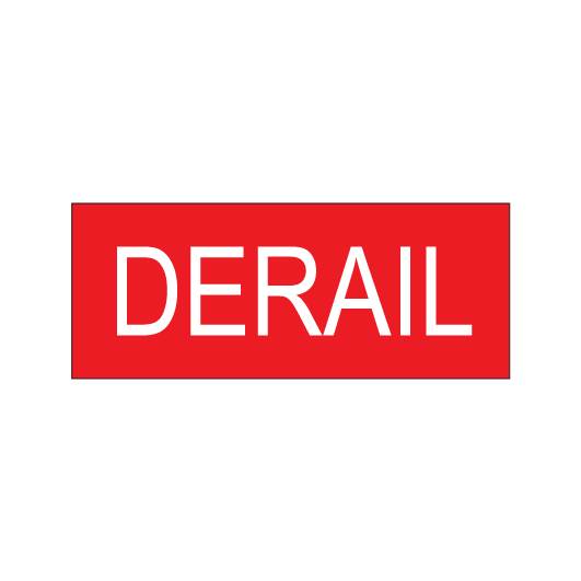
DERAIL signs
DERAIL signs:
- indicate that there is a derail device ahead, and
- have white text on a red reflective background, and
- are provided where movements can be made towards derail devices, and the devices are not protected by a fixed signal or an indicator.
Qualified Workers controlling shunting must remove derail devices before authorising shunting movements beyond a DERAIL sign.
DISTANT WARNING signs
DISTANT WARNING signs with a blue flashing light are used during pilot staff working if there is no signal within 2500m of a STOP sign being used to protect points or a crossover.

Electric train signs
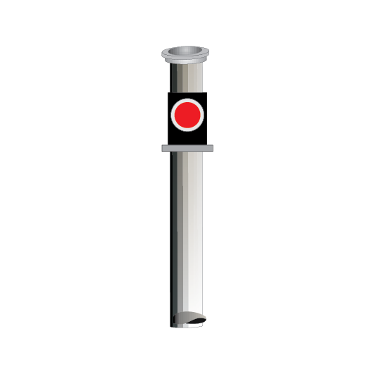
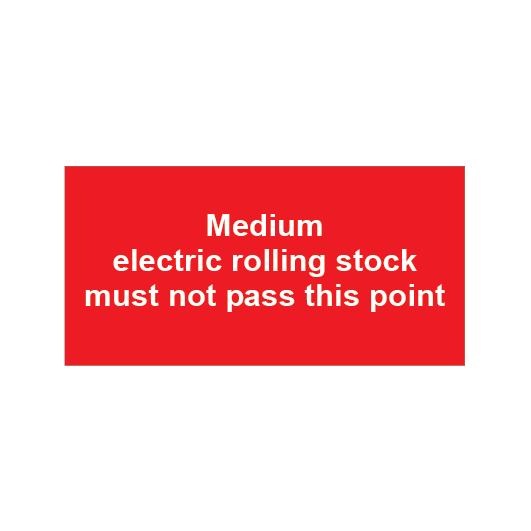
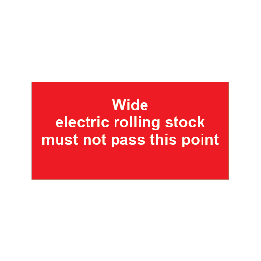
Electric rolling stock prohibition signs
Electric rolling stock prohibition signs:
- indicate the point that medium width or wide width electric rolling stock must not pass, and
- have white text on a red background.
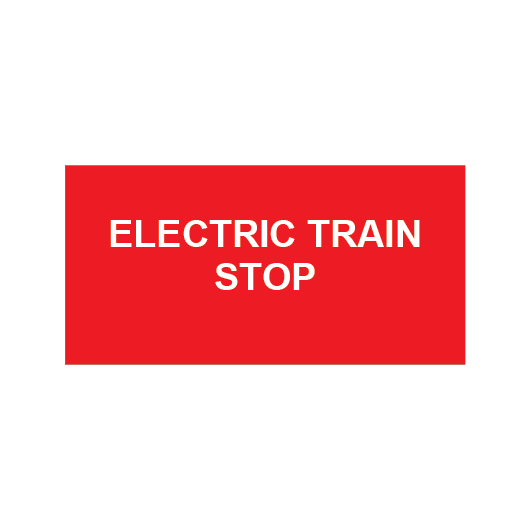
Electric train STOP signs
Electric train STOP signs are provided to advise Drivers of electric trains that a non-electrified portion of track exists ahead.
Two types of signs are:
FIGURE 21: Examples of electric train STOP signs.

Located adjacent to points that can give access to a non-electrified portion of track. Drivers must not proceed if points are set for the non-electrified portion of track unless authorised to travel with pantographs lowered.
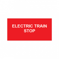
Located at a point where the overhead wiring for a portion of track ends. Drivers of electric trains must not proceed unless they are authorised to travel with pantographs lowered.
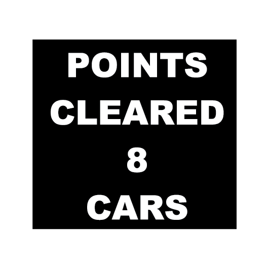
POINTS CLEARANCE signs
POINTS CLEARANCE signs are provided at some locations to tell Drivers of 8-car electric trains that the train is clear of the relevant points.
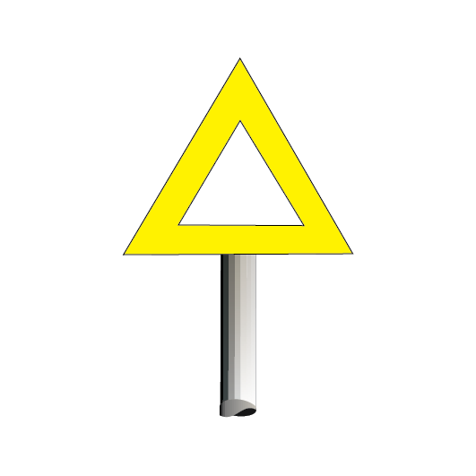
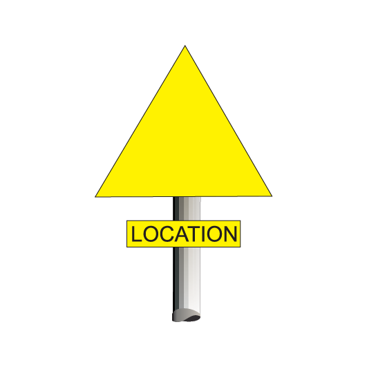
LANDMARK and LOCATION signs
LANDMARK and LOCATION signs are reflective yellow signs that may be placed on the approach side of a location where rail traffic may be required to stop.
The location may be:
- a signal, or
- a STOP sign.
Drivers and Track Vehicle Operators must respond to LANDMARK and LOCATION signs in accordance with NSG 606 Responding to signals and signs.
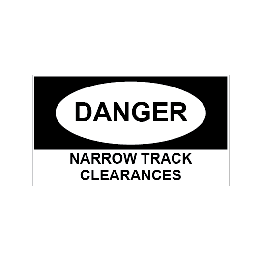
NARROW TRACK CLEARANCES sign
Warning signs are placed in locations where there is restricted clearance between:
- vehicles on adjacent lines
- the track and other infrastructure or buildings.
Workers performing shunting at locations with these warning signs must not stand between a moving vehicle and a vehicle standing on an adjacent line. Qualified Workers performing shunting must act in accordance with NTR 420 Shunting and marshalling.
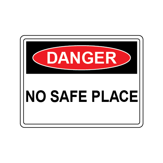
NO SAFE PLACE signs
NO SAFE PLACE signs are provided at locations in the Network where there is no safe place to retreat to avoid being struck by rail traffic.
NO WHISTLE signs
Unless necessary for safety, rail traffic whistles must not be sounded where no whistle signs are located.
Prohibitive signs
If a signal carries a prohibitive sign, Drivers and Track Vehicle Operators must follow the directions on the sign.
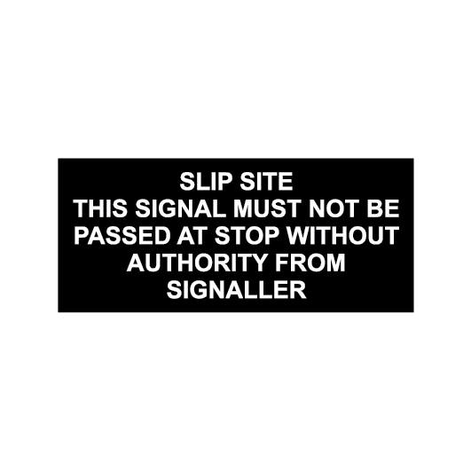
SLIP SITE signs
Signals fitted with a SLIP SITE sign are interlocked with slip detectors to respond to landslips.
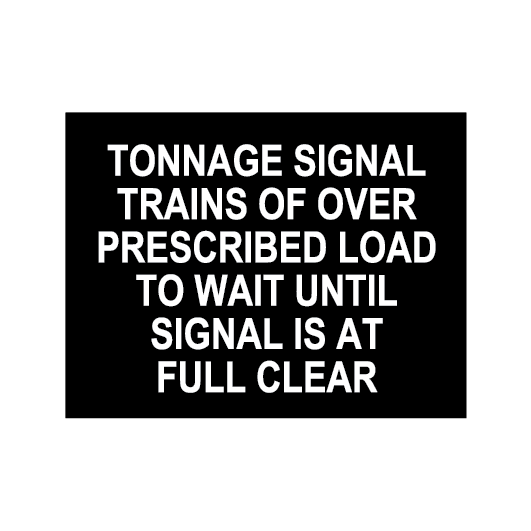
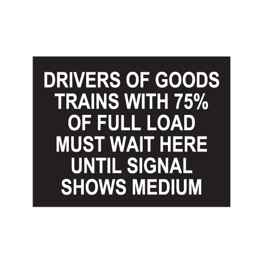
TONNAGE signs
A TONNAGE sign might be fitted on or near a signal placed before a rising grade.
Tonnage signals are absolute signals for prescribed trains. There may also be a tonnage (T) indicator.
If the T indicator is lit, Drivers of prescribed trains may ignore the instructions on the TONNAGE sign.

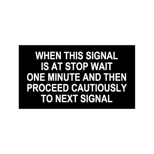
Starting or home/starting signal signs
Some starting or home/starting signals in bidirectional Rail Vehicle Detection territory have prohibitive signs.
Distant signal and repeater signal signs
Distant signals and colour light repeater signals that can display STOP have signs with white reflective text on a black background.
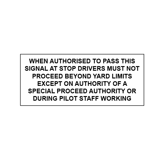
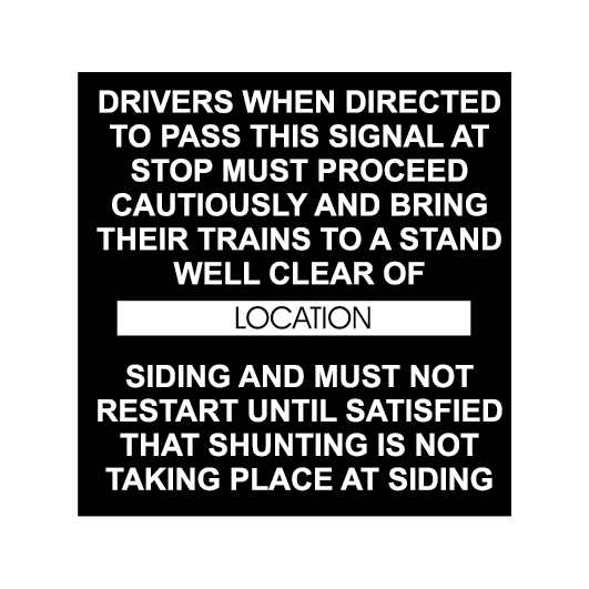
Intermediate siding signs
Signals that protect intermediate sidings must be passed only in accordance with the instructions on the sign.
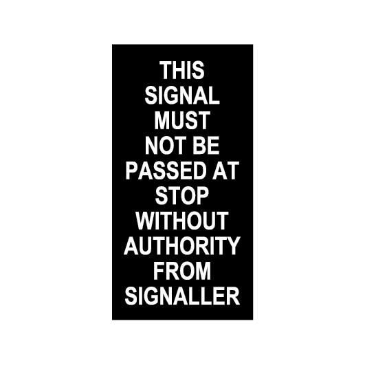
Absolute signal signs
Signals fitted with an absolute signal sign must not be passed at STOP without the Signaller’s authority.
Signal key switch sign
Signals with a signal key switch sign displayed must not be passed at STOP without authority.
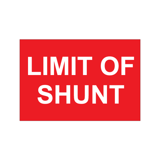
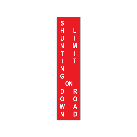
SHUNTING LIMIT signs
SHUNTING LIMIT signs:
- indicate the limit to which a shunting movement may be made on a running line, and
- have white text on a red reflective or illuminated background.

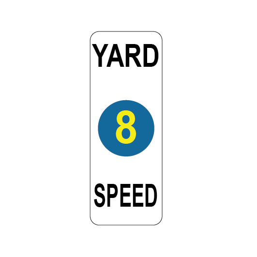
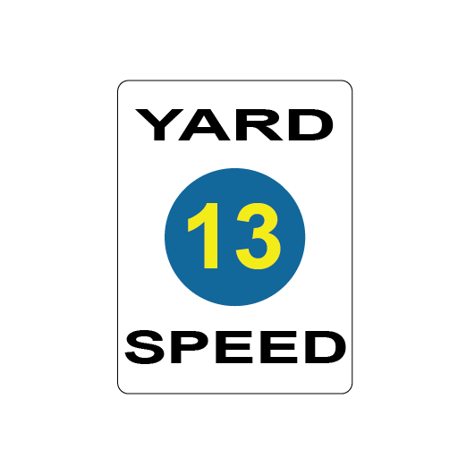
Speed signs
Drivers and Track Vehicle Operators must make sure that the front of a train or track vehicle passes a speed sign at or below the speed given by the sign.
If speed signs allow an increase in speed, Drivers and Track Vehicle Operators must not increase speed until the rear of the train or track vehicle has passed the speed sign.
If there is no advertised speed or speed sign, rail traffic must not travel faster than 25km/h.
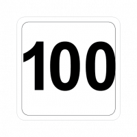
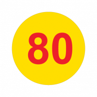
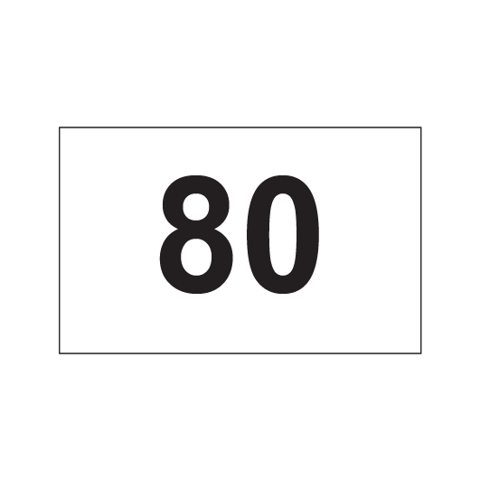
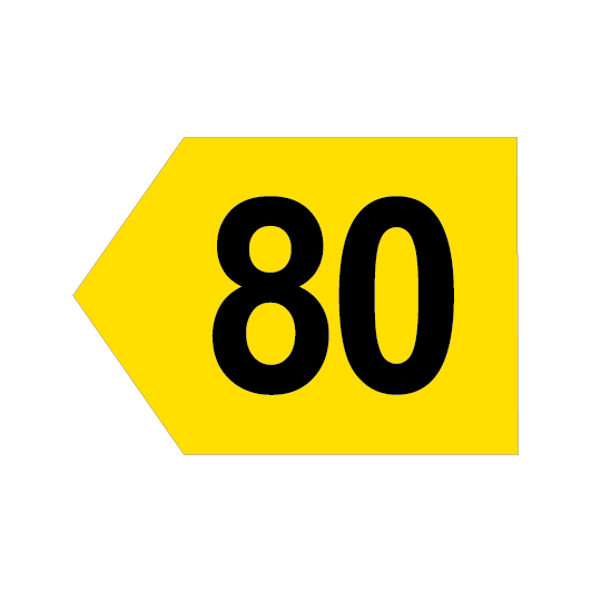
Permanent track speed signs
Permanent track speed signs:
- are fixed next to the line at locations nominated in the Train Operating Conditions (TOC) manual, and
- show the maximum speed for the portion of track.
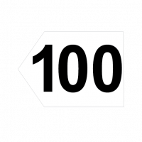
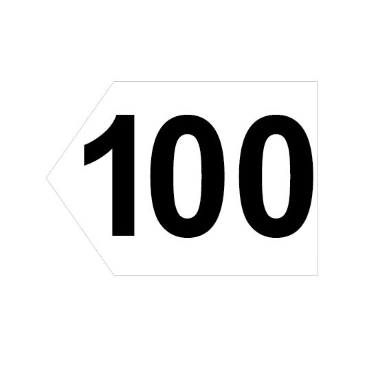
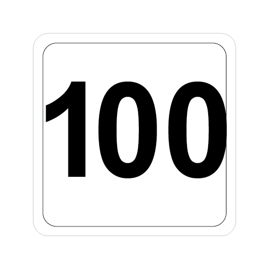
Figure 45: Examples of track speed signs.
Sign type - NORMAL
Applies to:
- All Trains (unless a higher speed is indicated by a MULTIPLE UNIT or XPT speed sign)
- All track maintenance vehicles
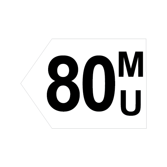
Sign type - MULTIPLE UNIT
Applies to:
- K, T, V and Y sets
- A, B, D, H and M sets, Endeavour, Hunter, Xplorer and XPT (unless a higher speed is indicated by an XPT speed sign)
Sign type - XPT
Applies to:
- A, B, D, H and M sets (maximum speed specified in the TOC manual must not be exceeded)
- Endeavour, Hunter and Xplorer (maximum speed specified in the TOC manual must not be exceeded)
- XPT
Single yellow background speed signs apply to all rail traffic.
A white background speed sign without the MU designation, by itself, or under a yellow background speed sign applies only to:
- A, B, D, H and M sets, and
- Endeavour, Hunter and Xplorer, and
- XPT.
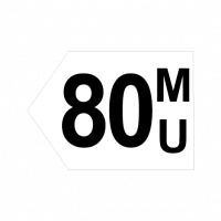
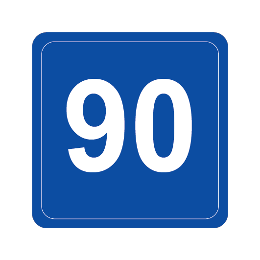
Figure 46: Examples of track speed signs.
Sign type - GENERAL
Applies to:
- Locomotive hauled passenger and freight trains (up to 1500 metres long)
- All track maintenance vehicles
- Rail Motors and 620 class diesel trains
Sign type - MEDIUM
Applies to:
- K, T, V and Y sets
Sign type - HIGH
Applies to:
- A, B, D, H and M sets (maximum speed specified in the TOC manual must not be exceeded)
- Endeavour, Hunter and Xplorer (maximum speed specified in the TOC manual must not be exceeded
- XPT
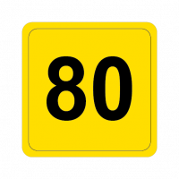
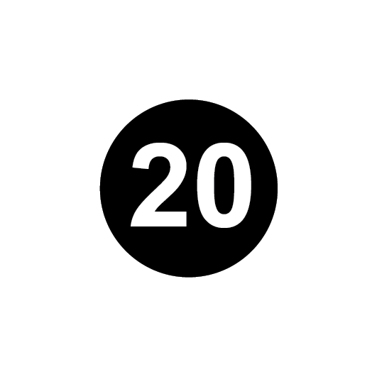
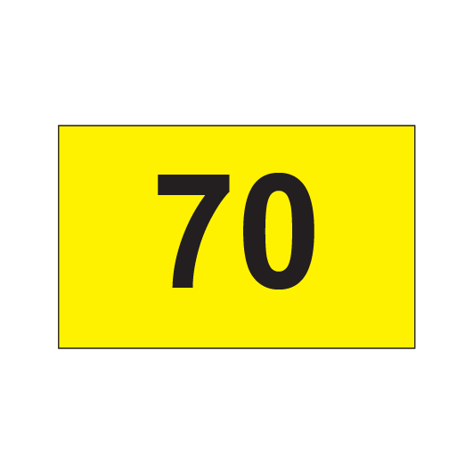
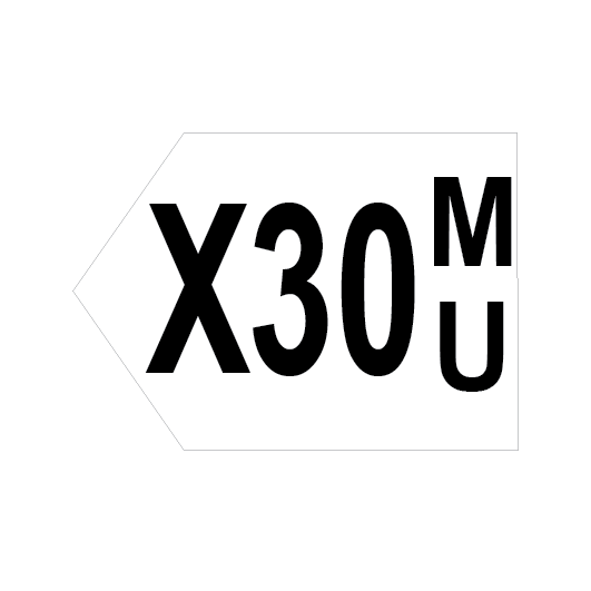
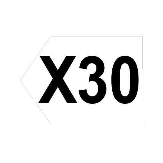
Turnout speed signs
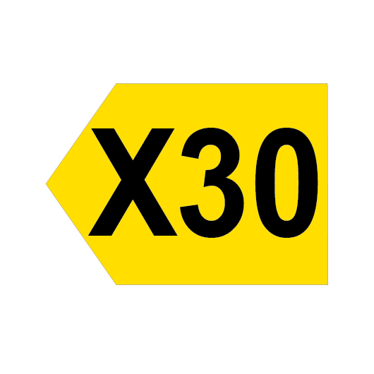
Turnout speed signs have black text on a yellow background. The letter “X” before the numbers on a permanent speed sign shows the maximum speed for the turnout.
If there is no speed sign at a turnout, rail traffic must not travel faster than 25km/h through the turnout.
Drivers and Track Vehicle Operators must maintain the correct speed until the last vehicle clears the turnout.
FIGURE 47: Examples of turnout speed signs.
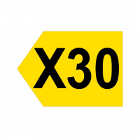
Sign type - NORMAL TURNOUT
Applies to:
- All Trains (unless a higher speed is indicated by a multiple unit or XPT turnout speed sign)
- All track maintenance vehicles
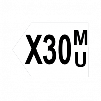
Sign type - MULTIPLE UNIT TURNOUT
Applies to:
- K, T, V and Y sets
- A, B, D, H and M sets, Endeavour, Hunter, Xplorer and XPT (unless a higher speed is indicated by an XPT turnout speed sign)
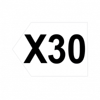
Sign type - XPT TURNOUT
Applies to:
- A, B, D, H and M sets (maximum speed specified in the TOC manual must not be exceeded)
- Endeavour, Hunter and Xplorer (maximum speed specified in the TOC manual must not be exceeded)
- XPT
Advisory speed signs
Advisory speed signs are provided where there is not enough signal sighting distance to allow rail traffic to stop if required at the second signal ahead.
FIGURE 48: Advisory speed sign.
Sign type - ADVISORY SPEED SIGN
Applies to:
- Freight and Passenger services (excepting XPT, Xplorer, Endeavour, Hunter and electric trains)
Drivers must reduce train speed so that the train is travelling at the indicated speed before the front of the train reaches the first signal ahead.
If the first signal ahead shows a CLEAR indication, normal speed may be resumed.
Intermediate train stop advisory speed signs
These signs may be placed before an intermediate train stop. If the signal beyond this sign indicates STOP, train speed must be at or below the indicated speed before the front of the train passes the sign.
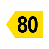
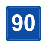
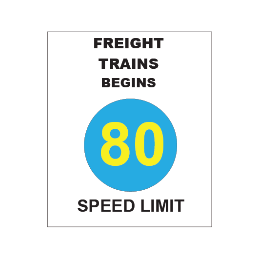
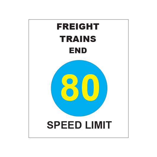
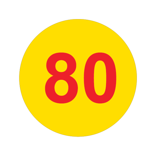
Freight train speed signs
Freight train speed signs:
- indicate a maximum speed of 80km/h for freight trains travelling inside the area as shown in the Train Operating Conditions (TOC) manual, and
- have yellow text on a blue background.
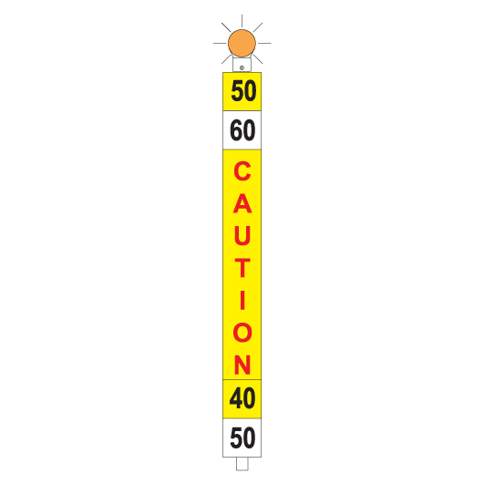
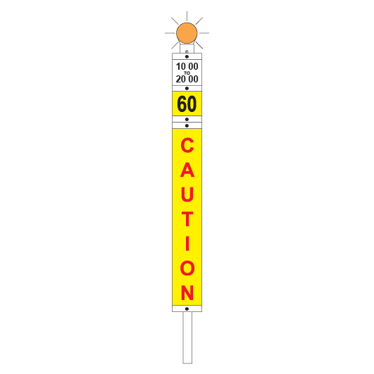
Temporary speed restrictions
Temporary speed restrictions may be imposed, altered, or withdrawn only by appropriate Maintenance Representatives.
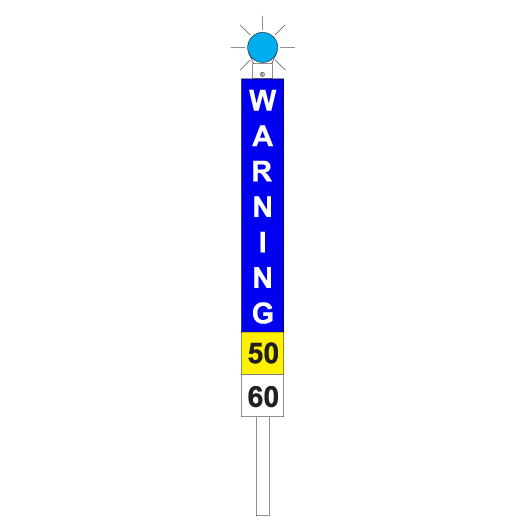
Temporary speed restrictions are imposed by using temporary speed signs that are a combination of:
- WARNING signs
- CAUTION signs
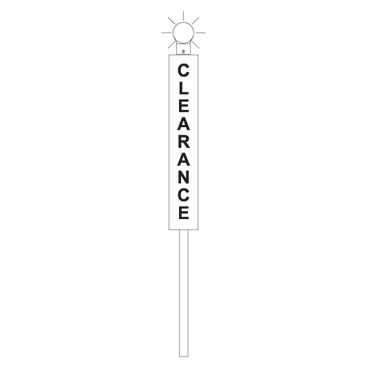
- CLEARANCE signs
Temporary speed signs take precedence over permanent speed signs and must be placed on all lines that give access to the affected portion of track.
Signallers must warn Drivers or Track Vehicle Operators entering an affected portion of track about speed restrictions until:
- the Maintenance Representative says they can travel at normal speed, or
- temporary speed signs have been installed, or
- affected portions of track are protected by Handsignallers.
If temporary speed restrictions are continued, the Maintenance Representative must advertise the restrictions in a Speed Restriction Notice.
Flashing lights
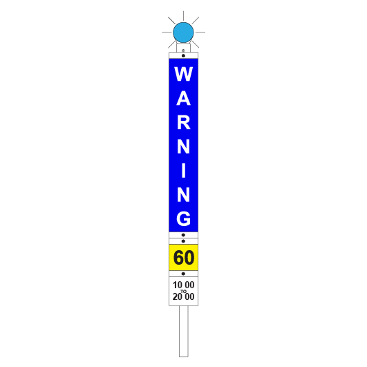
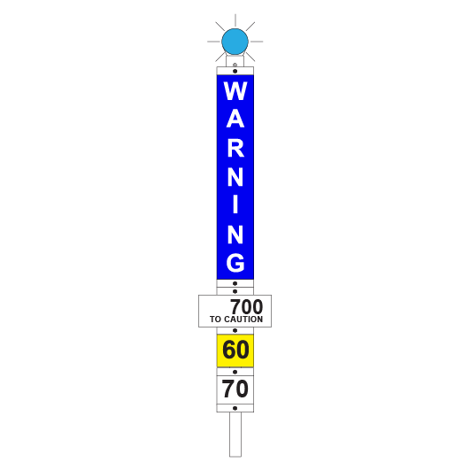
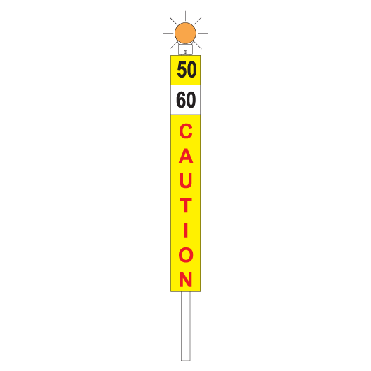
Flashing lights must be fitted to the top of temporary speed signs:
- blue for a WARNING sign
- amber/orange for a CAUTION sign
- white for a CLEARANCE sign.
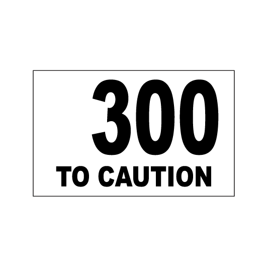
Speed plates
Speed plates are fitted to the bottom of a WARNING sign and to the top of a CAUTION sign to indicate what speed restrictions apply.
Speed plates:
- have black text on a white background, or
- have black text on a yellow background.
A single yellow background speed plate applies to all rail traffic.
A white background speed plate, by itself or under a yellow background speed plate, applies only to passenger trains.


Single speed restriction
If there is a single speed restriction, temporary speed signs must be placed as follows:
| Sign | Placement | Meaning |
|---|---|---|
| WARNING | 2500m before the affected portion track | Temporary speed restriction ahead. The bottom of the sign shows the limit that applies in the affected portion. |
| INTERMEDIATE WARNING | On an adjacent line with a track speed of 40km/h or less if a warning sign cannot be placed at 2500m before the affected portion of track | Temporary speed restriction ahead. The bottom of the sign shows the limit that applies in the affected portion and the distance to the CAUTION plate. |
| Beyond the departure end of a platform to allow the Driver to see the sign while stopped at the last platform before the affected portion of track | ||
| CAUTION | 50m before the affected portion track | Temporary speed restriction. The top of the sign shows the limit that applies in the affected portion. |
| CLEARANCE | 50m beyond the affected portion of track | Temporary speed restriction no longer applies. Normal speed may be resumed. |
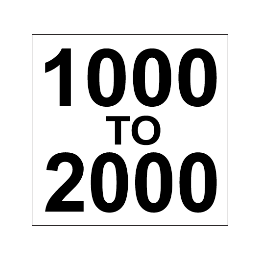
Multiple speed restrictions
If there are multiple speed restrictions within 2500m of each other, temporary speed signs must be placed as follows:
| Sign | Placement | Meaning |
|---|---|---|
| WARNING | 2500m before the first affected portion of track | Temporary speed restrictions ahead. The bottom of the sign shows the limit that applies in the first affected portion. |
| INTERMEDIATE WARNING | On an adjacent line with a track speed of 40km/h or less if a warning sign cannot be placed at 2500m before the affected portion of track | Temporary speed restriction ahead. The bottom of the sign shows the limit that applies in the affected portion and the distance to the CAUTION sign. |
| Beyond the departure end of a platform to allow the Driver to see the sign while stopped at the last platform before the affected portion of track | ||
| CAUTION | 50m before each affected portion of track, and 50m beyond each affected portion, except the last | Temporary speed restrictions. The top of each sign shows the limit that applies from the current CAUTION sign to the next. If required, the bottom of each sign shows the limit that applies between the next CAUTION sign and the CAUTION sign after that. |
| CLEARANCE | 50m beyond the last affected portion of track | Temporary speed restrictions no longer apply. Normal speed may be resumed. |
STOP signs
STOP signs:
- may be passed only if authorised, and
- have white text on a red reflective background.


When used for pilot staff working, a steady red light must be fixed to the STOP sign.
Timing track marker sign
Timing track marker signs are placed at a location for which the timing will begin, to allow the PROCEED aspect for a signal to conditionally clear.

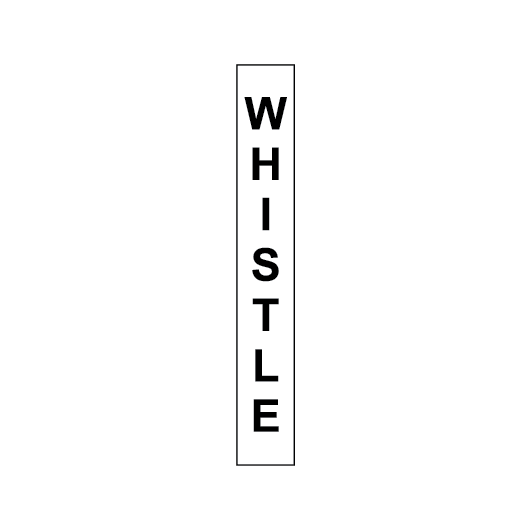
WHISTLE signs
Drivers and Track Vehicle Operators must sound the whistle before the front of rail traffic passes a WHISTLE sign.
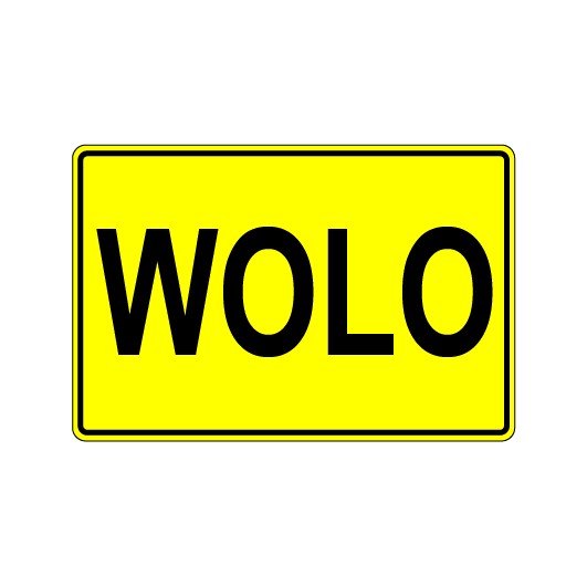
WOLO speed restriction signs
WOLO speed restriction signs are located at the locations nominated in the Train Operating Conditions (TOC) manual and are displayed while WOLO speed restrictions apply.
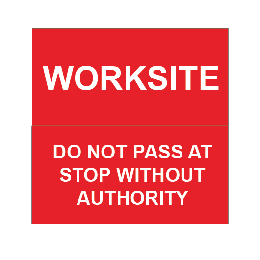
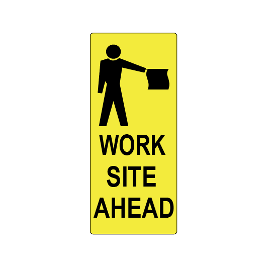
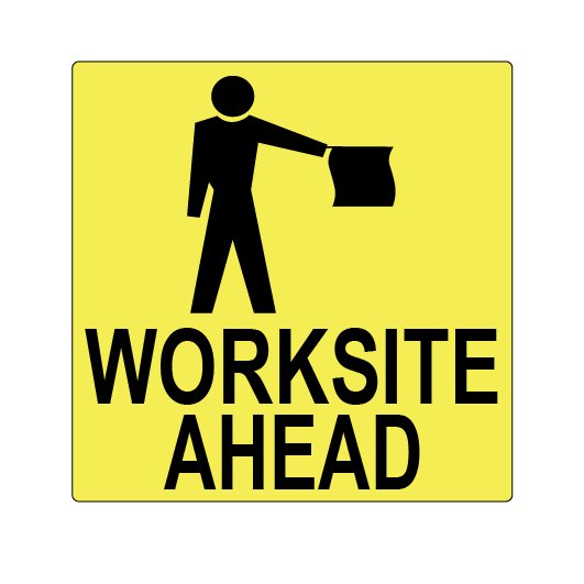
WORKSITE warning signs
WORKSITE warning signs are located beyond the departure end of a platform to allow the Driver to see the sign while stopped at the platform.
WORKSITE warning signs act as a reminder that an inner Handsignaller is located ahead.
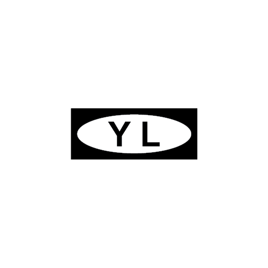
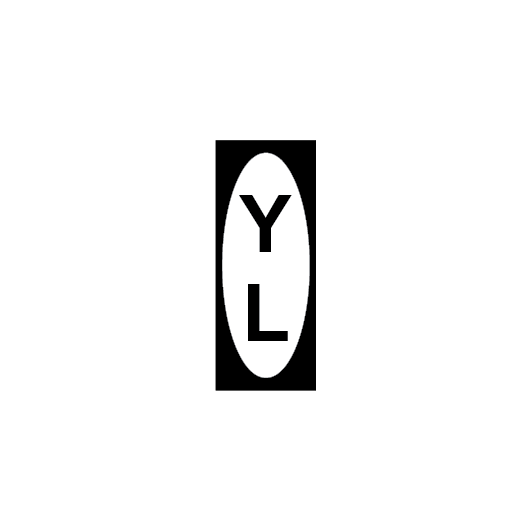
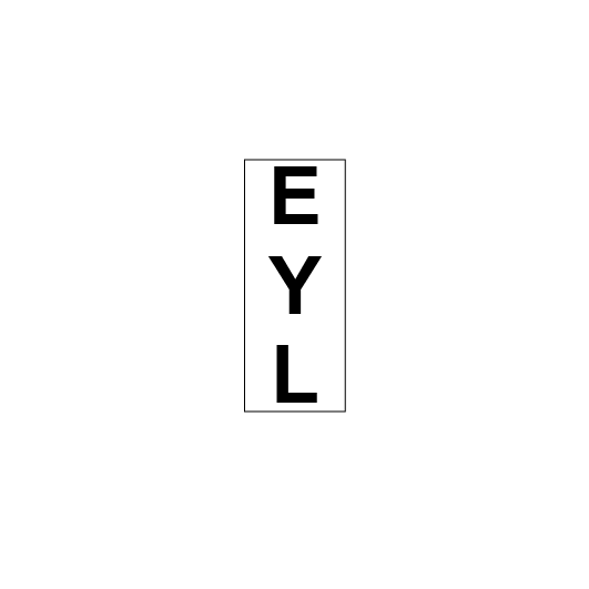
YARD LIMIT signs
Yard limit signs:
- define the limits of yards, and
- define the end of a section.
Drivers and Track Vehicle Operators must respond to YARD LIMIT signs in accordance with:
