Description
This document describes the procedure for protecting Type F level crossings.
Not what you are looking for? See more Procedures
Introduction
Handsignallers protect Type F level crossings when roadside or pedestrian warning equipment is faulty or cannot be activated.
Roadside warning signs and equipment
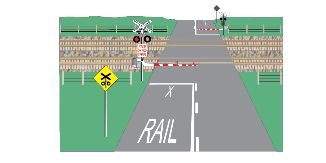
Type F level crossings have roadside advance warning signs and flashing warning lights. Some Type F level crossings have one or more of:
- bells and other audible warning devices
- full-booms or half-booms that lower across a road to stop road traffic
- booms or gates to stop pedestrian traffic
- advance warning lights, which give a more distant warning to road users.
Type F level crossing warning equipment is of failsafe design. If the controlling track-circuit fails:
- lights and bells operate, and
- booms lower to stop road and pedestrian traffic.
The warning equipment continues to operate until:
- the fault is fixed, or
- operation is cancelled by the Emergency switches.
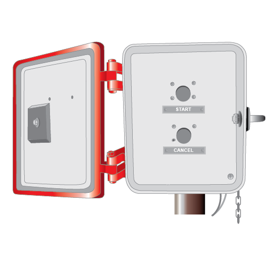
Type F level crossing switches
Switches to control warning equipment are located in locked boxes at or near level crossings.
| Switch Box | Purpose | Fitted to |
|---|---|---|
TEST | Activates all warning equipment | Some Type F level crossings |
MANUAL OPERATION | If fitted, activates all warning equipment | Some Type F level crossings |
SHUNTERS | If fitted, activates all warning equipment | Some Type F level crossings |
EMERGENCY | Key locked switches used to deactivate some or all of the level crossing warning equipment | All Type F level crossings |
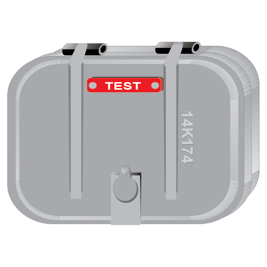
Test switch
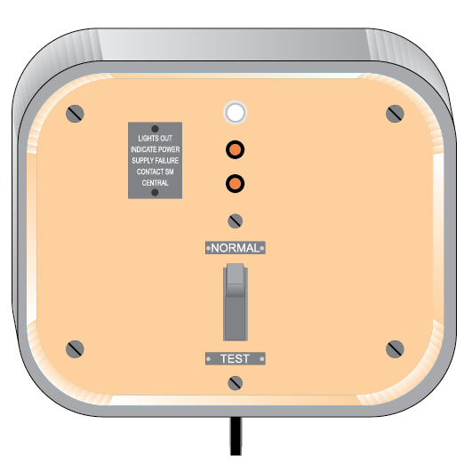
Test switch boxes have a Test switch and two lights. When the Test switch is set to TEST, it activates all warning equipment. When lit, the lights indicate that battery power is available.
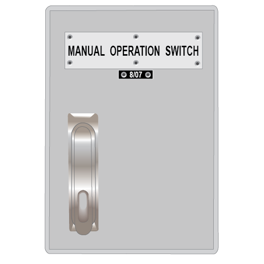
Manual Operation switch
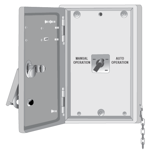
Manual operation switch boxes have a switch with two positions, AUTO and MANUAL. When this switch is set to MANUAL it activates all warning equipment.
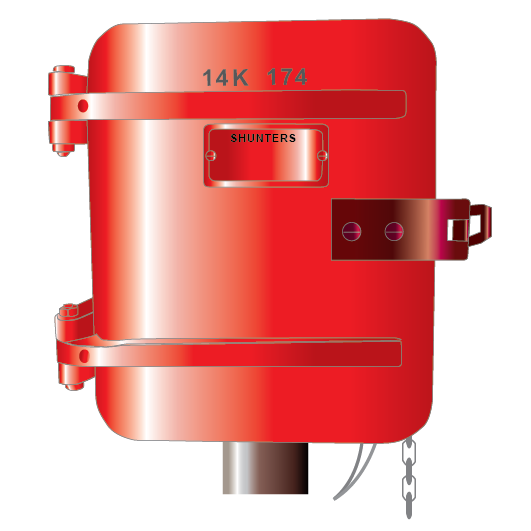
Shunters switch
Shunters switch boxes have a two-position switch. Level crossings with shunters switches usually have a box on each side of the level crossing. When the switch is operated, it activates all warning equipment. Once activated, the crossing equipment can be deactivated by operating the shunters switch on either side of the crossing.
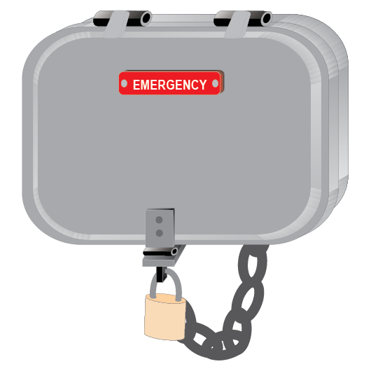
Emergency switches
There are two types of emergency switch boxes.
One type has individual switches for Sydney and Country side lights, Sydney and Country side booms, and bell.
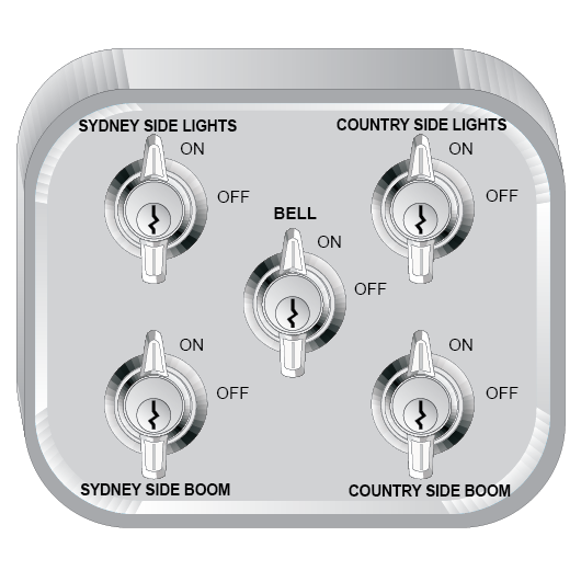
| Switch | Purpose |
|---|---|
LIGHTS | Key locked in the ON position. When switched to the OFF position switches off power to the lights |
BELLS | Key locked in the ON position. When switched to the OFF position it switches off power to the bells |
BOOMS | Key locked in the ON position. When switched to the OFF position it switches off power to the booms |
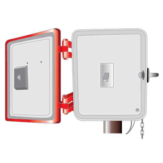
The other type of emergency switch box has a MASTER EMERGENCY switch and individual BOOM switches for each boom (if fitted). Level crossings with this type of switch box also have a manual operation switch box.
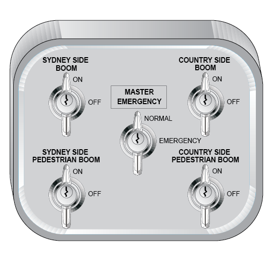
| Switch | Purpose |
|---|---|
MASTER EMERGENCY | Key locked in the NORMAL position for automatic operation. When switched to the EMERGENCY position, it deactivates the warning equipment |
BOOMS | Key locked in the ON position. When switched to the OFF position, it switches off power to the booms |
If warning equipment cannot be operated
Warning equipment may not operate due to:
- mains and battery power loss, or
- damage to the warning equipment, or
- the warning equipment has been disconnected.
If warning equipment cannot be operated, refer to NPR 717 Using emergency roadside warning equipment.
If rail traffic movement does not activate warning equipment
Some rail traffic movements do not operate warning equipment. For example, wrong running-direction movements or vehicles that do not reliably activate track‑circuits.
If a Manual Operation switch is fitted
Qualified Worker
- Open the manual operation switch box.
- Set the manual operation switch to MANUAL to activate the warning equipment and stop road and pedestrian traffic.
- After road and pedestrian traffic has stopped, give a PROCEED handsignal to the Driver or Track Vehicle Operator.
- When rail traffic has fully cleared the level crossing, and if no other rail traffic is approaching, set the manual operation switch to AUTO to allow road and pedestrian traffic to proceed.
- Lock the manual operation switch box.
If a Manual Operation switch is not fitted
Qualified Worker
- Get the Test keys from the controlling location.
- Get the Signaller’s authority to manually operate the level crossing.
- Open the Test box.
- Set the Test switch to TEST to activate the warning equipment and stop road and pedestrian traffic.
- After road and pedestrian traffic has stopped, give a PROCEED handsignal to the Driver or Track Vehicle Operator.
- When rail traffic has fully cleared the level crossing, and if no other rail traffic is approaching, set the Test switch to NORMAL to allow road and pedestrian traffic to proceed.
- Lock the Test box.
- Return the keys to the controlling location.
Isolating warning equipment
Warning equipment may need to be isolated because:
- a fault or track-circuit failure is making it operate continuously, or
- planned work on track might make it operate continuously.
Do not switch off warning equipment that is operating continuously before you have spoken to the Signaller and made sure that there is no rail traffic approaching.
If individual switches for lights, bell and booms are fitted
Isolating warning equipment that is operating continuously
Handsignaller
- Get the Test and Emergency keys, a hand-held STOP sign, and rope (if necessary) from the controlling location.
- Get the Signaller’s authority to manually operate the level crossing.
- Open the Test and Emergency switch boxes.
- Insert the keys in the Emergency switches.
- Set the Boom switches to OFF. Keep Boom switches in the OFF position until the warning equipment has been restored to normal operation.
- Make sure that all other Emergency switches are ON.
- Tie a rope to the top cross-brace of each road boom. Lift booms by hand and tie them securely in the fully raised position.
Be careful not to damage the booms.
- Do not tie pedestrian boom arms.
- Set the Light switches and Bell switches to OFF.
Do not allow road or pedestrian traffic to proceed while warning equipment is operating.
Isolating warning equipment for planned work on track
Handsignaller
- Activate the warning equipment to stop road and pedestrian traffic by:
- setting the Manual Operation switch (if fitted) to MANUAL, or
- setting the test switch to TEST.
Do not allow road or pedestrian traffic to proceed while warning equipment is operating.
- Tie a rope to the top cross-brace of each road boom.
- Deactivate warning equipment to allow road and pedestrian traffic to proceed by:
- setting the Manual Operation switch if fitted to AUTO or
- setting the Test switch to NORMAL.
- Tie road booms securely in the fully raised position.
Be careful not to damage the booms.
- Do not tie pedestrian boom arms.
- Set the Emergency switches to OFF.
- Keep Boom switches in the OFF position until the warning equipment has been restored to normal operation.
Managing road and pedestrian traffic
- If pedestrian booms or gates have failed, open them to allow pedestrians to cross as required.
- When rail traffic approaches the level crossing, activate the warning equipment by:
- setting the Light switches and Bell switches to ON, or
- setting the Manual Operation switch (if fitted) to MANUAL, or
- setting the Test switch to TEST.
- Use a hand-held STOP sign to stop road and pedestrian traffic.
- Make sure that pedestrian gates are closed, or pedestrian booms are lowered.
- After road and pedestrian traffic has stopped, give a PROCEED handsignal to the Driver or Track Vehicle Operator.
- When rail traffic has fully cleared the level crossing, and if no other rail traffic is approaching, to allow road and pedestrian traffic to proceed:
- set the Light switches and Bell switches to OFF, or
- set the Manual Operation switch (if fitted) to AUTO, or
- set the Test switch to NORMAL.
If a Master Emergency switch is fitted
Isolating warning equipment that is operating continuously or for planned work on track.
Handsignaller
- Set the Master Emergency switch to EMERGENCY.
Do not allow road or pedestrian traffic to proceed while warning equipment is operating.
- If a road boom has failed in the lowered position, and the boom does not raise automatically:
- set the applicable Boom switch to OFF, and
- tie a rope to the top cross-brace of the boom, and
- lift the boom by hand, and
- tie the boom securely in the fully raised position, and
- do not operate the Boom switch for the tied boom before the warning equipment has been restored to normal operation.
While the Master Emergency switch is set to EMERGENCY, the signals immediately either side of the crossing may return to STOP.
- Do not tie pedestrian boom arms.
Managing road and pedestrian traffic
- If pedestrian booms or gates have failed, open them to allow pedestrians to cross as required.
- When rail traffic approaches the level crossing, set the Manual Operation switch to MANUAL to activate the warning equipment.
- If booms cannot be lowered, use a handheld STOP sign to stop road and pedestrian traffic and tell the Signaller that the warning equipment has been activated.
- Make sure that pedestrian gates are closed, or pedestrian booms are lowered.
The protecting signals immediately either side of the crossing will not clear until the level crossing equipment has activated, and the booms are lowered.
If the protecting signals cannot be cleared, the protecting signal must be passed at STOP in accordance with NSG 608 Passing signals at STOP.
- After road and pedestrian traffic has stopped, give a PROCEED handsignal to the Driver or Track Vehicle Operator.
- When rail traffic has fully cleared the level crossing, and if no other rail traffic is approaching, set the Manual Operation switch to AUTO to allow road and pedestrian traffic to proceed.
Resuming normal operation
If warning equipment is isolated due to a fault or track-circuit failure, a Signals Maintenance Representative must certify the warning equipment as working correctly.
Signaller
- Tell Handsignallers to test the level crossing and restore it to normal operation.
- Record the details in permanent form.
Handsignaller
- Make sure that the Test switch is set to NORMAL.
- Make sure that all Emergency switches are ON.
- Make sure that the Master Emergency switch (if fitted) is set to NORMAL.
- Make sure that the Manual Operation switch (if fitted) is set to AUTO.
- Remove the keys from the Emergency switches.
- Untie any ropes securing booms in the fully raised position.
- Set the Test switch to TEST.
- Check that all warning equipment works correctly.
- Untie any ropes from the top cross-brace of road booms.
- Return the Test switch to NORMAL.
- Check that all warning equipment stops operating.
- Lock the Test, Emergency and Manual Operation switch boxes.
- Tell the Signaller that the level crossing is operational.
- Arrange for the Test and Emergency keys, the hand-held STOP sign, and the rope to be returned to the controlling location.